Control Points Advanced Workflow: Multi-Scan Merging
This guide describes the different approaches to using control points in the field with the NavLive Radius scanner. There are multiple ways to use control points for different objectives and it is important you think carefully about your goals and workflow to have the best experience and results.
Alignment Methods
Control points can be captured by the NavLive Scanner in several ways, depending on your equipment, site, and accuracy requirements. Before choosing a method, it’s worth understanding the two types of control point referenced throughout this guide:
- Local control points: Captured by the NavLive scanner during a scan, with no external reference — their coordinates exist only within that scan’s own coordinate space.
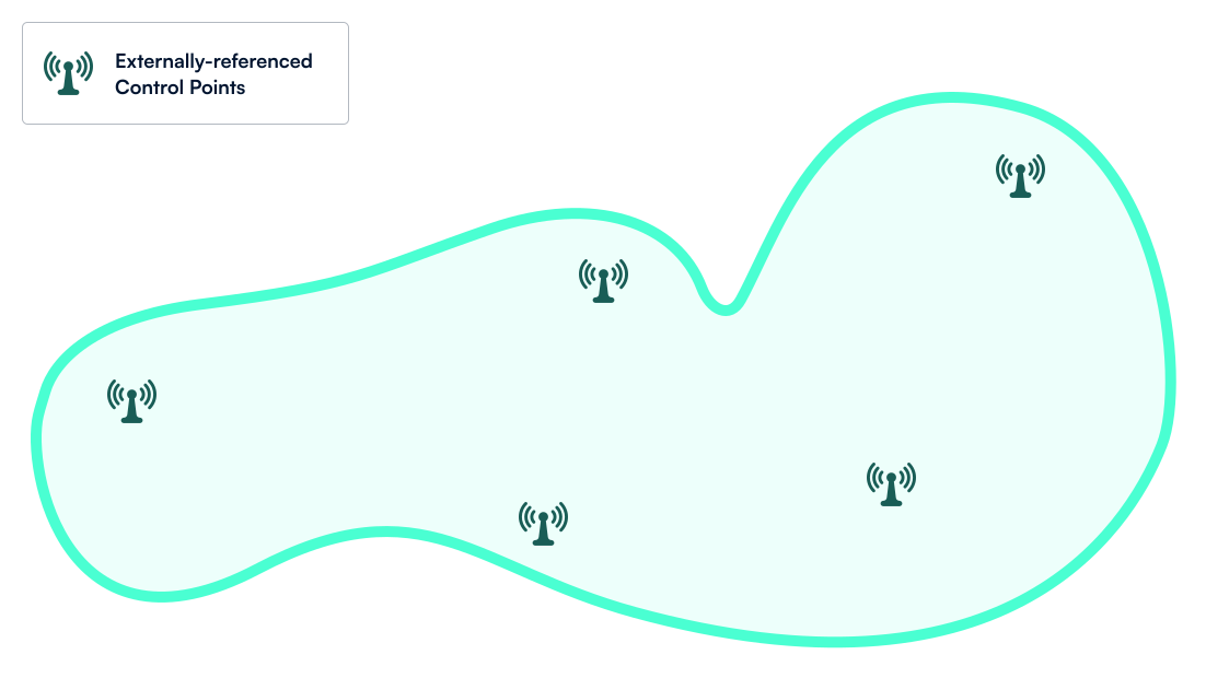
- Externally-referenced control points: Points with known, pre-measured coordinates, captured using external surveying equipment and provided to NavLive via a reference file.
This method is the gold standard for high-accuracy surveying and georeferencing. It works by capturing precise control point locations using professional surveying equipment, such as a total station or RTK-GPS. You then export these coordinates as a CSV file, then import it into NavLive to align your scan data against them.
Requirements
At least 3 control points (although ideally 4 or more), spread across different heights and locations. The more spatial variation between points, the better your alignment.
Tips and Best Practices
If you’re confident in the accuracy of your external control points, use non-rigid alignment. This lets the point cloud adjust slightly to match your control points precisely.
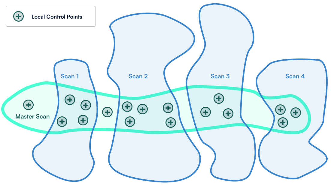
This method is ideal if you don’t have external survey equipment but still want all your scans in one unified coordinate space. Capture a single master scan covering all key areas, with at least 3 control points overlapping each subsequent scan you want to align.
Workflow:
- Complete and process your master scan, along with any subsequent scans.
- Export the control point CSV file generated by the master scan.
- Upload that CSV into each sub-scan you want to align.
Tips and Best Practices
These user-defined control points (with no external reference) are sometimes called “local” or “virtual” control points.
Note: Your merged dataset is only as accurate as your master scan, so take extra care capturing that first pass.
The fastest option in the field, with more flexibility during processing.
The workflow for this method requires capturing multiple scans, making sure each one shares some identifiable structure with the others. Stairwells and columns, for example, work well.
These shared features let you align the scans visually later, without registering control points on site. Once scanning is complete, download the raw point cloud files and align them manually in third-party software such as CloudCompare or Revit, using the overlapping structures as your reference points.
Best for:
Teams who want the quickest possible on-site capture and are comfortable handling cloud-to-cloud registration back in the office.
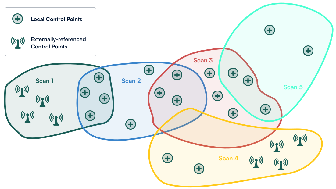
With this method, scans are captured sequentially in overlapping sections. For example, Scan 1 covers Floors 1–2, Scan 2 covers Floors 2–3, and Scan 3 covers Floors 3–4.
Each scan shares at least 3 control points with the one before it, chaining them together into a single continuous model.
Best for:
Large, multi-storey, or complex sites where external survey points aren’t available and a single master scan isn’t practical.
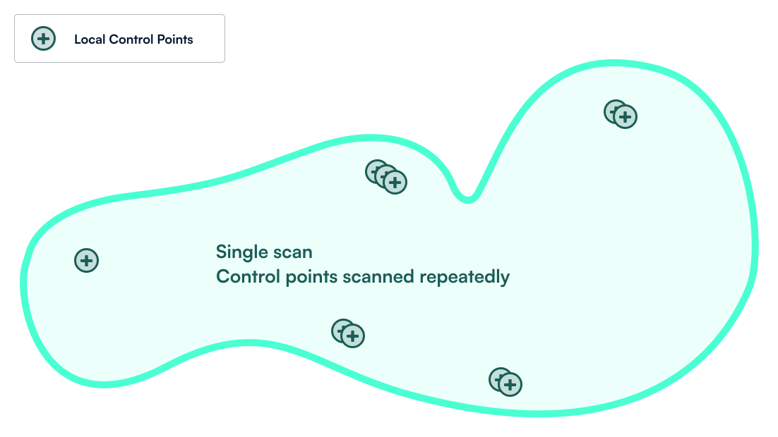
Capture the same control points several times throughout the scan to help reduce any drift that might occur. For example, you might capture control points at the start of the scan that you return to later. This provides information to the mapping algorithm that you have returned to a previous location and the map can be re-optimised.
Best for:
Large scans with big loops, such as walking the full perimeter of a building with no intermediate loop closures.
Tips and Best Practices
- Aligning a scan with itself will not change the scan at all (e.g., exporting the control points from a single scan and reuploading to the same scan will not change the point cloud).
- If the exact location of control points is well-known, then any of the control point alignment methods may be used to move the scans into approximately the correct location, then the scans can be manually aligned to meet user requirements (Method 3).
Note: This method only works if your control point tagging is accurate. Precise tagging reduces drift; inaccurate tagging can make your final map less accurate, not more.
Summary
| Alignment Method | Supported in NavLive | Best Used For |
|---|---|---|
| Method 1: Externally-Referenced | Yes | Maximum accuracy, survey grade, georeferencing |
| Method 2: Master Scan | Yes | Medium-to-large sites without external survey tools |
| Method 3: Manual (Third-Party) | Yes | Fast field capture; office-based alignment workflows |
| Method 4: Daisy-Chained | Live Beta | Multi-story/extended sites without a master scan |
| Method 5: Single Scan Drift Reduction | Yes | Reducing drift in very large environments with few opportunities for loop closures |
Example Control Point Files
The files below are provided as examples of control point files to use in an alignment workflow:
- external_reference_points.csv: surveyed reference points
- ground_floor.csv: master scan control points, aligned to the reference points
- basement.csv and upper_levels.csv: sub-scan control points, aligned to the ground floor. These two can be added in any order, as each aligns independently to the ground floor rather than to each other.
Note: These files include control point data only, not raw scan data, so they demonstrate the alignment logic rather than the full capture-to-alignment workflow.
Appendix: Daisy-Chained Scan Workflow
As of September 2026, NavLive’s standard portal workflows do not support daisy-chained control point alignment (Method 4). We therefore have developed a workaround method to support customers during this time.
Instructions:
Step 1: Collect all your control point CSV files. These can be downloaded from the portal using the “Export local CPs” button in the Control Points tab. You can also add control points with external references.
Step 2: Go to the control point alignment tool at: http://controlpoints.navlive.ai/
Step 3: Upload all individual control point CSV files to this box
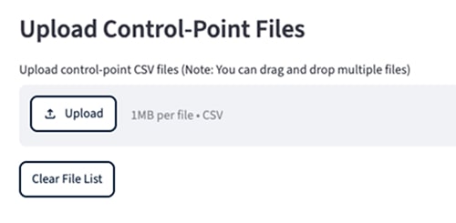
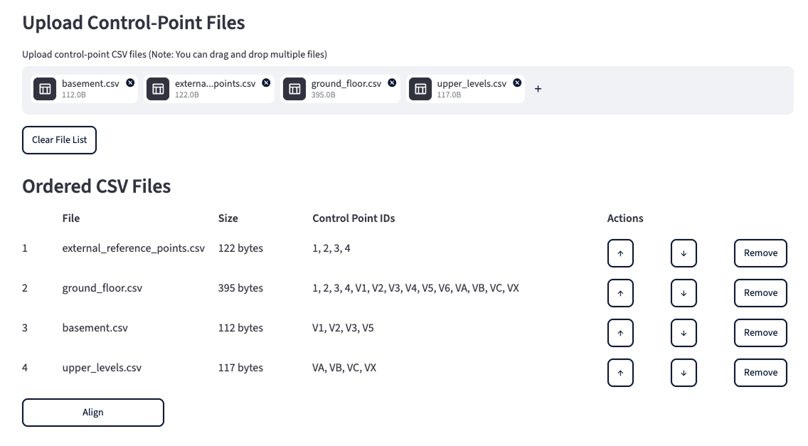
Step 4: Use the up/down arrows to order the csv files in the order of alignment you would like.
For example, you might have 3 scans with a combination of virtual and externally referenced control points. This tool attempts to align each scan to the previous set of scans. In this example, you might order the scans as follows:
1. External reference points csv
2. Ground floor and external scan (align to the 1st scan)
3. Upper floor scan (aligned to combination of 1st and 2nd scans)
4. Basement scan (aligned to combination of 1st, 2nd, and 3rd scans)
IMPORTANT: Each successive scan must have at least 3 control points in common with the previous scans. If this is not the case, then the alignment will fail.
Step 5: Press “Align” and view the results
You will see the following:
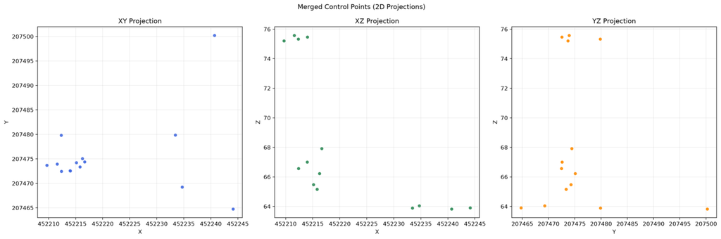
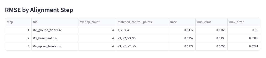
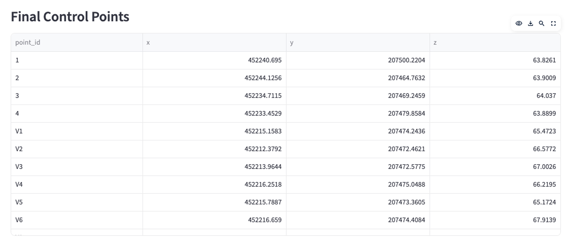
Tip: You can change the order of the files and rerun alignment as many times as required.
Step 6: Download the merged csv file using the button at the bottom of the page.
Step 7: Upload this new merged control point csv file to each of the scans you wish to align on the portal. The outputs should then all be aligned to the same coordinate system.
Tip: It is recommended to use non-rigid alignment for situations where you have very high confidence in control point locations (e.g., from externally-referenced CPs) and rigid alignment if there is lower confidence in CP locations.
Note: This method may accumulate small errors between each scan that is being aligned. For example, each time you align one scan to another, there may be 1- 3 cm of error that may accumulate.